Industrial Controls
Content
- Mandate
- Project Portfolio
- Technologies
- Project Showcase: POPS+
- Virtual Commissioning
- Publications
- Team Members
- Team Alumni
Mandate
The Industrial Control Systems team designs, develops, commissions and maintains PLC-based control systems that control, interlock and monitor CERN’s Electrical Power Converters and Static VAR compensators (SVC). The team covers every layer of these control systems, from field buses and PLC hardware and software up to the operators HMIs and SCADA integration, as well as functional safety of it all.
Project Portfolio
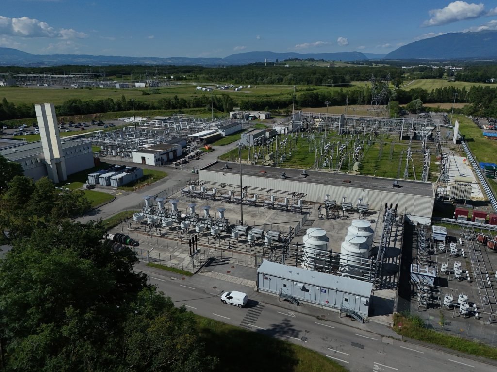
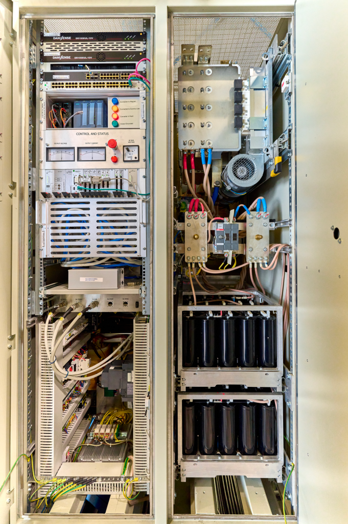
- Control systems for power converters in range of ~15 MW to ~150 MW, and single to 20 PLCs in a control system:
- Power System for PS-B main magnets (POPS-B)
- Power System for PS main magnets (POPS)
- Control and Interlock System of SPS main power supplies (SPS Mains CIS)
- Control systems for Static Var Compensators (SVC) and stable filters:
- 13 SVCs around the accelerator complex.
- Control systems for commercial power converters
- Around 600 converters used by AD, ELENA, ISOLDE and LEIR.
- Control system for HL-LHC Circuit Disconnector Boxes for the inner triplet circuits of High Luminosity LHC.
- Various temperature monitoring systems for transformers.
Technologies

Project Showcase: POPS+
Powering the PS Main Magnets
POPS+ is the project to upgrade POPS, the power system that supplies the PS (Proton Synchrotron) main magnets. Its role is to generate the fast-changing magnetic fields required during accelerator operation.
The system can handle up to 60 MW and works by exchanging energy between large capacitor banks and the magnet loads
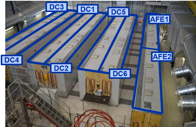
At its core, POPS+ consists of:
- 2 Active Front-End (AFE) converters connected to CERN’s 18 kV electrical network
- 6 DC-DC converters which exchange energy with the magnet loads (3-level NPC converter architecture)
- A distributed control system coordinating the power converters and the rest of the installation
From POPS to POPS+
During LS3 the existing POPS system is being consolidated and upgraded.
One of the main improvements is redundancy: an additional spare AFE and a spare DC-DC converter are added. This means that a converter failure does not necessarily require the system to stop, improving reliability and reducing downtime.
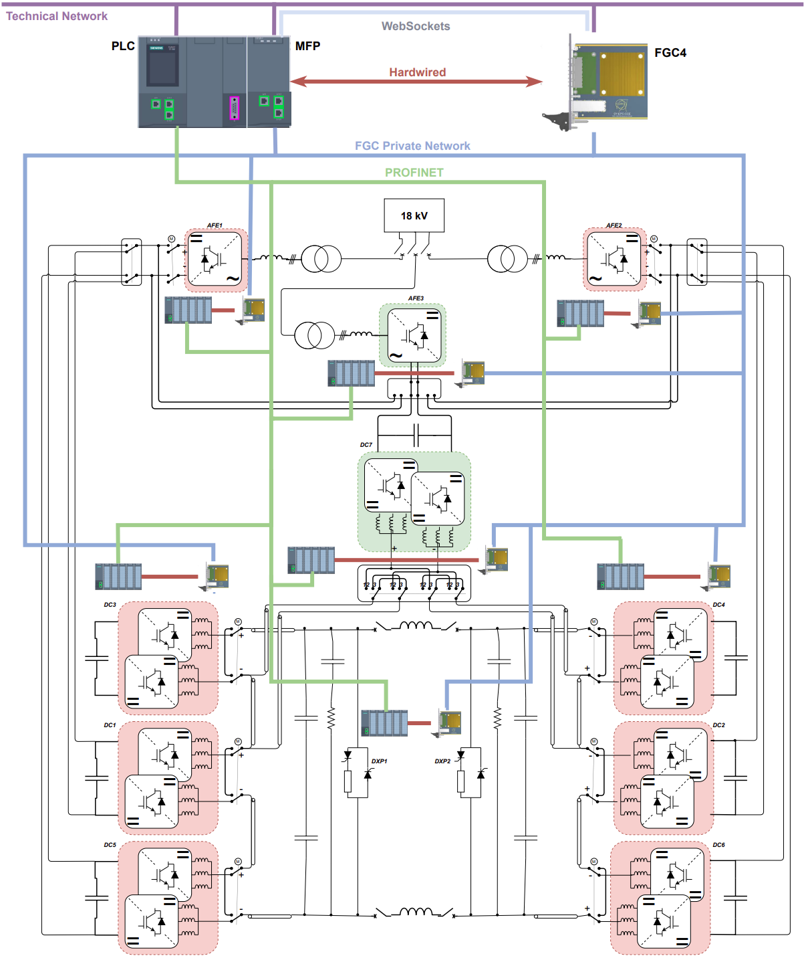
The control system is also being modernized. The existing control system (a combination of commercial controllers with CERN’s FGC2) is replaced by the new generation FGC4 controllers, and by a new distributed PLC based with PROFINET fibre optic network and WinCC OA SCADA.
Centralized Control
The PLC acts as the orchestrator of the system.
It coordinates the different FGC4 controllers, switches, interlocks, and system states. It also monitors the configurations and manages the transitions between the different operating modes.
This centralized approach makes the system easier to operate, diagnose, and maintain.
The PLC application is developed using CERN’s UNICOS framework, with SCADA providing system supervision.
Utilizing Hardware In the Loop (HIL) Simulation
Before connecting the control system to the real 60 MW installation, POPS+ can be tested using a Hardware-in-the-Loop (HIL) setup.
The HIL system uses a Speedgoat real-time simulation platform together with MATLAB, Simulink and Simscape to reproduce the behavior of the electrical system.
Simplified models of the converters, magnets, switches and protection systems are connected to the real control software.
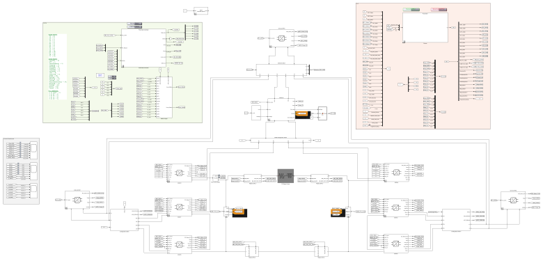
This makes it possible to test the complete control system before the real equipment is available or ready for operation.
What can be tested?
The HIL environment allows engineers to safely test:
- Complete POPS+ operating sequences
- PLC state machines and interlocks
- FGC4 control loops
- Converter coordination
- Communication interfaces
- Alarms and protection functions
- Fault and corner cases such as pre-charging faults, voltage fluctuations and short circuits
The simulations can be repeated as often as necessary, without risking the real power converters or magnets. The tests are also automated and executed in GitLab pipelines, following a CI/CD approach, allowing the control software to be continuously tested and validated as it evolves.
Simulating a Complete Cycle
The HIL model can reproduce the complete POPS+ operating sequence, from startup to shutdown.
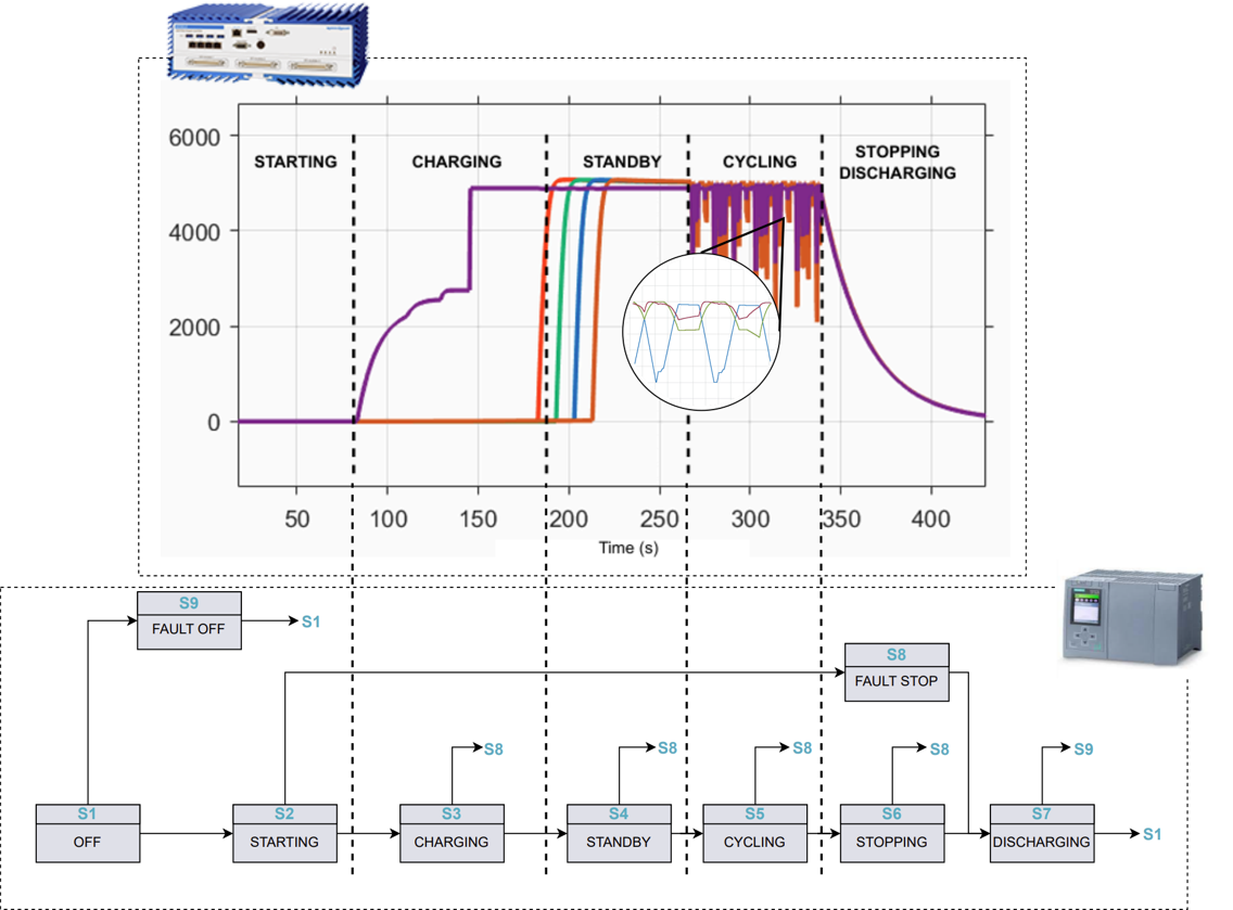
A typical sequence consists of:
Pre-charging → Standby → Capacitor charging → Cycling → Stopping
During the cycling phase, energy is exchanged between the capacitor banks and the magnets, generating the required fast-cycling magnetic fields.
At the end of the cycle, the capacitor banks are safely discharged.
Virtual Commissioning
Virtual commissioning extends this approach by allowing the control system and its software to be tested in a fully simulated environment before commissioning the actual equipment. By connecting a physical PLC to a digital model of the plant, we can validate functionality, familiarize operators with the system, verify interfaces, and optimize control logic under realistic operating conditions.
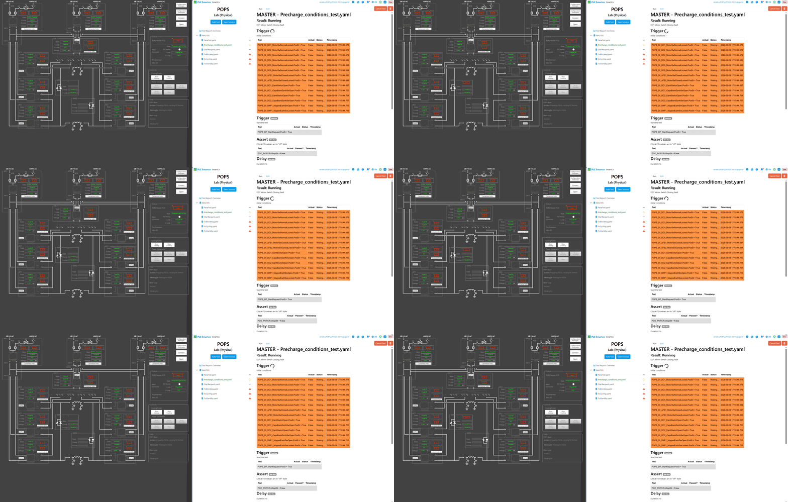
Together, HIL simulation and virtual commissioning allow much of the system to be tested before commissioning the physical installation.
This helps to:
- Reduce commissioning time and effort
- Detect issues at an early stage
- Reduce risks during system commissioning
- Improve system reliability and robustness
- Enable safe operator training
Publications
Team Members
Current members of the CCS Industrial Controls Team, ordered by start date.

Jose Manuel
de Paco Soto


Team Leader
Automation Engineer
at CERN since 2012-10

Walter
Niinimäki

Industrial Controls Engineer
at CERN since 2023-02

Janne
Bosch

Control Engineer
at CERN since 2025-10

Chris
Lawrence

Industrial Controls
Engineer
at CERN since 2026-06
Alumni
Former members of the CCS Industrial Controls Team, ordered by end date.
Zoran
Morrissey-Ralevic


Software Engineer
at CERN from 2025-09 to 2026-10

Marcos
Marin
Automation Engineer
at CCS from 2021-08 to 2026-04

Oleksandr
Minaiev

Automation Engineer
at CERN from 2024-10 to 2025-09

David
Carvalho


Control Software
Engineer
at CERN from 2019-03 to 2024-02

Liam Luigi
Cantu
Mechatronic Engineer
at CCS from 2023-04 to 2023-07
Silvie
Nemcova

Computer Security
Master Student
at CERN from 2022-03 to 2022-11

Maria del Mar
Gomez-Jordana
Embedded Systems
Master Student
at CERN from 2021-03 to 2022-04

Fernando
Jusdado
Automation Engineer
at CERN from 2018-06 to 2021-05

Michal
Dudek

Project Manager
Site Reliability Engineer
Software Engineer
at CERN from 2010-02 to 2018-07